Holodeck
Overview
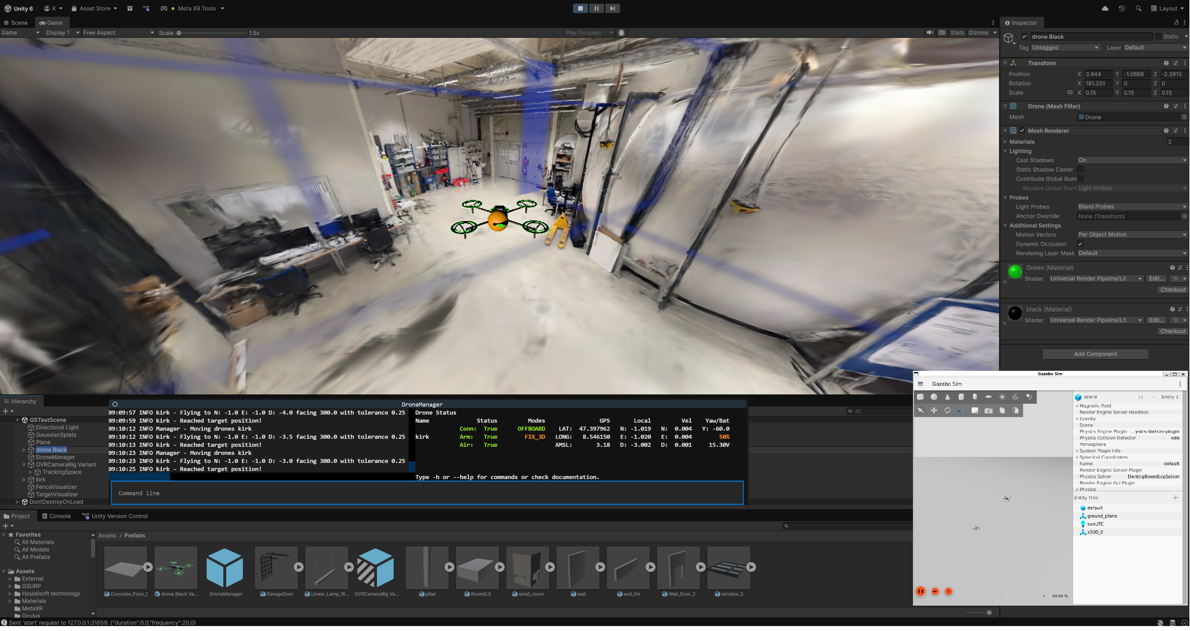
Holodeck is an example for the integration of DroneManager with modern simulation environments like Unity. It allows Users to control a real drone with a Playstation Controller via DroneManager while experiencing the virtual flight in a Unity Environment with enhanced perception through VR-Glasses (e.g. Meta-Quest Pro). This Docs Section explains how it works and how you can easily modify it or expand it for your UseCase. You can download this project on Github.
Installation
This guide covers the steps required to set up the Unity simulation environment.
Note
The Python-based DroneManager backend is a separate installation. Please refer to the Installation guide for instructions on setting up the Python environment and its dependencies.
Prerequisites
Before setting up the Unity project, ensure you have the following installed:
Unity Hub & Unity 6000.2.8f1: The project uses the Universal Render Pipeline (URP). And you have to use DX12 or Vulcan if you want to use GaussianSplatting (GSTestScene).
- Unity Android Build Support: Essential for Meta Quest VR development. In Unity Hub, ensure the following modules are added to your Editor version:
Android Build Support
Android SDK & NDK Tools
OpenJDK
Visual Studio 2022: Must be installed with the “Game development with Unity” workload (includes C# and required Unity integration tools).
Git: Required to clone the repository and manage any submodules.
Setting Up the Unity Project
1. Download the Project
Download the Project from the Github Project Page. You can download it from the releases. See the readme there for more information. We use GitHub as a file downloader because Unity VersionControl does not support public repos.
2. Open via Unity Hub
Launch Unity Hub.
Click Add > Add project from disk.
Navigate to and select the
Holodeck-Unityfolder.Ensure the Editor version is set to 6000.2.8f1*.
3. Install Dependencies
Once the project is open, verify the following in the Package Manager (Window > Package Manager):
Newtonsoft Json.NET: If not present, click the “+” icon, select “Add package by name,” and enter
com.unity.nuget.newtonsoft-json.XR Interaction Toolkit: (Optional) Required for VR functionality. Ensure this is installed and the “Oculus” or “OpenXR” provider is enabled in Project Settings > XR Plug-in Management.
Meta XR All-in-One SDK: Click the “+” icon, select “Add package by name,” and enter
com.meta.xr.sdk.all.
4. Dependencies for creating your own digital clone
Gaussian Splatting: Click the “+” icon, select “Add package by name,” and enter
org.nesnausk.gaussian-splatting.Git Installation: Alternatively, you can install the plugin directly from the Aras-P repository by selecting “Add package from git URL…” and entering:
https://github.com/aras-p/UnityGaussianSplatting.gitRequirements: The plugin requires Unity 2022.3 or newer and a GPU that supports DirectX 12 or Vulkan. Ensure these are enabled in your Project Settings > Player > Other Settings.
Usage
Setting Up a Custom Holodeck Scene
While the project provides a pre-configured Scenes/GSTestScene.unity with a GaussianSplatting Scan of our Lab and a Scenes/TestScene-01 without any GaussianSplatting Assets,
you may want to create a custom Digital Twin of your specific flight environment. Follow these steps to integrate the Holodeck logic into a new scene.
1. Scene Preparation
Create a new Unity Scene.
Ensure your environment scale is 1:1 (1 Unity unit = 1 Meter) to match the real-world GPS/Local coordinates.
Add your scan or any other assets.
2. Core Logic Integration
Orchestrator Object: Drag the
Prefabs/DroneOrchestratoras an empty GameObject in your scene.VRCamera: Drag and drop the
Prefabs/OVRCamera Rig Variantinto your sceneConfigure Ports: In the
UDPReceiveron theDroneOrchestratorempty GameObject in the inspector, set theserverIpandserverPortto match your Python backend.Delete the default “Main Camera.” Otherwise the VRCamera does not know which one to pick as main.
3. Gaussian Splatting
To create a high-fidelity digital twin of your environment, you need to capture spatial data using a mobile device (e.g., iPhone 15 Pro) equipped with LiDAR and CMOS sensors.
Download Scanning Apps: Install applications like Scaniverse or Luma AI from the App Store or Play Store.
Capture the Environment: Scan the entire room, ensuring every corner, edge, and surface is covered. Maintain high overlap between movements to ensure the Gaussian Splatting algorithm has enough depth information to reconstruct fine details.
Export Data: Export the processed scan as a .ply file. This file acts as the dense point cloud required for the Unity plugin.
For a reference of what a successful capture looks like, see this Luma AI Sample.
3.1 Import the Gaussian Splatting into Unity Scene
To load the Gaussian Splatting into your Unity scene, follow these steps:
Initialize and Import Assets:
Navigate to Tools > Gaussian Splatting to initialize the plugin after installation.
Create GaussianAssetSplats. %Image1gs here
Import the .ply file: Drag and drop the exported .ply file into the Assets folder of your Unity project.
Assign the .ply file:
Create or load Scene of GSTestScene
In the Inspector window, locate the Gaussian Splatting Renderer component.
Click the circle icon next to the PLY File field.
Select your imported .ply file from the list. %Image2gs here
Adjust Settings:
Scale: Ensure the scale of the object matches your environment. If the scan appears too small or too large, adjust the Scale values in the Transform component of the Gaussian Splatting object.
Position: Position the object at the origin (0, 0, 0) or at the desired location for your digital twin.
3.2 Generating k-DOP Colliders
- To enable real-time collision avoidance and path planning, follow these steps to extract geometric boundaries from Gaussian primitives:
%Image3kdop here
Analyze Splat Distribution: Use the GPU-accelerated algorithm to analyze the covariance and opacity (\(\alpha\)) of the splat distribution.
Synthesize Safety Shell: Generate a 14-DOP (Discrete Oriented Polytope) “safety shell” that serves as a lightweight, tight-fitting spatial proxy.
Export Asset: Utilize the standardized export module to encapsulate both the high-fidelity 3DGS data and the generated k-DOP colliders into a single Prefab FBX asset.
3.3. Alternative to modify environment with building Prefab
For scenarios where automated generation is not ideal, you can manually enhance the environment using pre-configured assets: %Image4prefabs
Locate Assets: Open the
Assets/Prefabsfolder in the Unity Project window.Add Colliders: Drag and drop the desired pre-made mesh objects into the Hierarchy or Scene view.
Manual Positioning: Use Unity’s transform tools to manually align these meshes with the Gaussian Splatting visualization to represent physical obstacles.
Physics Integration: These prefabs are pre-equipped with mesh colliders, ensuring they are correctly interpreted by the simulation’s physics engine and pathfinding algorithms.
Running the Simulation
Once the scene is set up, follow this execution order:
Start the Backend: Run your DroneManager Python script. It will begin listening for a connection request.
Enter Play Mode: Press Play in the Unity Editor.
Handshake: The
UDPReceiverwill automatically send a start request. Once received, the Python backend will begin streaming telemetry.Verification: The DroneOrchestrator should spawn the corresponding drone in your scene. MetaQuest VR headsets will automatically pickup a UnityScene and load into the cam. Make sure to have it setup correctly. This was the most unreliable component on our side. Read the Meta Setup Guide carefully for your chosen hardware.
Tip
If you want to quickly test your setup without creating a scene from scratch, open Assets/Scenes/TestLevel-1. It contains a fully functional configuration with a demo environment and all script references already linked.
System Architecture
Overview
The Holodeck system is built on a Decoupled Architecture. This means the flight logic (the “Brain”) runs in a Python environment, while the simulation and visualization (the “Body”) run in Unity. They communicate via a low-latency UDP network protocol.

Data Flow & Lifecycle
The integration follows a continuous loop to ensure the Digital Twin stays synchronized with the real-world drone state:
Backend (Python/DroneManager):
The
External Pluginallows to expose certain data for other applications by packaging drone telemetry, mission stages etc. into a JSON dictionary.The
OptiTrack Plugincan grab the tracked position of drones of an OptiTrack System and update the drones telemetry accordingly.The
Stream Pluginpicks up the vitual camera stream from unity and renders it in an external window via open-cv.The
Controller Pluginallows to control a real or simulated drone via a commercial PlayStation Controller.
Transport (UDP):
The backend streams this JSON via UDP to Unity. This is “fire-and-forget,” ensuring the drone’s flight is never delayed by rendering frames in Unity. On the otherhand Unity is able to transmit the stream of a virtual camera via TCP and JPEG images back to DroneManager for external display via Open-CV.
Frontend (Unity/Holodeck):
The
UDPReceivercatches the packet and parses it according to the DroneDataClasses struct.The
DroneOrchestrator(Unity Side) checks if the drone exists in the scene. If not, it spawns a new one.The
DroneControllerupdates the 3D model’s position and orientation.The
Displaysupdate AR elements (Fences/Waypoints) based on the latest mission data.The
CameraSpringArmattaches to the first drone and hosts the VR-Camera.
Feedback (Optional):
The
CameraStreamercan send the virtual FPV view back to Python for Computer Vision analysis.
Key Technologies
Unity 3D: Used for simulation and VR rendering.
JSON (Newtonsoft.Json): The standard data format used to bridge the gap between Python and C#.
Asynchronous Threading: Used in Unity to handle network traffic without causing “lag” or frame drops in the VR headset.
VR (XR Interaction Toolkit): Provides the immersive interface for the pilot via the OVR Camera Rig.
Unity Scripts
DroneOrchestrator & Controller
The DroneOrchestrator acts as the central manager, controlling the lifecycle of drone GameObjects based on the UDP stream. The DroneController acts as the local agent, handling the physical movement and smoothing for a specific drone.
DroneOrchestrator: Architecture
The DroneOrchestrator does not control flight physics; it synchronizes the Unity Scene state with the Python backend state.
1. Lifecycle Reconciliation (The Update Loop)
Every frame, the Orchestrator compares the incoming JSON dictionary against its internal managedDrones dictionary:
Spawn: If a Drone ID exists in the JSON but not in Unity, it instantiates the
DronePrefab.Update: If an ID exists in both, it passes the data to the
DroneController.Despawn: If an ID exists in Unity but is missing from the JSON (disconnection), it destroys the GameObject.
2. Data Routing
The Orchestrator acts as a data router. It unpacks the DroneData object and forwards specific components to the relevant scripts on the drone:
Telemetry: Sent to
DroneController.UpdateData().Geofence: Extracted from
data.fenceand sent toFenceDisplay.UpdateFence().Waypoints: Extracted from
data.target[0](Nested List) and sent toTargetDisplay.UpdateTarget().
3. Automatic Camera Attachment
The Orchestrator enforces a “First-Pilot” rule for VR comfort.
* Logic: The first drone spawned is automatically assigned as the target for the CameraSpringArm.
* Result: The VR player immediately enters “Chase Mode” behind the first connected drone.
Orchestrator Configuration
Attach this script to your persistent prefered GameObject or use the DroneOrchestrator Prefab.
Field |
Type |
Description |
|---|---|---|
Drone Prefab |
|
Required. The template object to spawn. (See “Prefab Requirements” below). |
Follow Camera |
|
Reference to the main VR camera rig. If left empty, the script attempts to find it via |
DroneController: Movement Logic
The DroneController handles the raw coordinate transformation and smoothing.
Coordinate Transformation It converts the backend’s NED (North-East-Down) system to Unity’s (Z-X-Y) system.
Interpolation (Smoothing) Since UDP updates (~20Hz) are slower than the VR Frame Rate (~90Hz), raw position updates would look jittery. The controller uses interpolation to smooth this gap:
Position: Uses
Vector3.Lerpwith a configurable smoothing factor.Rotation: Uses
Quaternion.Slerpto find the shortest arc between angles.
Prefab Requirements
For the system to function correctly, the Drone Prefab assigned to the Orchestrator must have the following component structure:
Root Object: *
DroneController(Required for movement) *FenceDisplay(Optional, for safety boundaries) *TargetDisplay(Optional, for waypoint AR)Child Objects: * 3D Model (Mesh) * (Optional) Virtual Camera for
CameraStreamer
Code Snippet: Data Propagation
This snippet from DroneOrchestrator.cs illustrates how data is unpacked and routed to the visualizers.
// Example: Routing Target Data
TargetDisplay targetVis = actor.GetComponent<TargetDisplay>();

// 1. Check if target data exists in JSON
if (droneData.target != null && droneData.target.Count > 0)
{
    // 2. Extract the first target from the nested list
    List<float> targetCoords = droneData.target[0];

    // 3. Pass only the coordinates to the visualizer
    targetVis.UpdateTarget(targetCoords, actor.transform.position);
}
DroneDataClasses
The DroneDataClasses.cs file defines the schema for the UDP telemetry stream. These classes serve as the deserialization target for the Newtonsoft.Json library, mapping the incoming JSON string from the Python backend to C# objects.
Data schema (JSON Structure)
The system expects a JSON payload structured as a dictionary of drones and (optionally) missions. Below is the expected format, including the nested target list and fence boundaries:
{
  "drones": {
    "Drone_01": {
      "position": [10.5, -5.2, -2.0],
      "gps": [48.7667, 11.4226, 370.0],
      "velocity": [0.1, 0.0, -0.05],
      "attitude": [0.0, 2.5, 90.0],
      "mode": "OFFBOARD",
      "conn": true,
      "armed": true,
      "in_air": true,
      "rtsp": "rtsp://192.168.1.55:8554/stream",
      "fence": [10.0, -10.0, 10.0, -10.0, 0.0, -10.0, 1.0],
      "target": [[12.0, -5.0, -2.0]]
    }
  },
  "missions": {
    "Mission_Alpha": {
      "flightarea": [0.0, 10.0, 0.0, 10.0, 0.0, -5.0],
      "stage": "EXECUTION",
      "drones": ["Drone_01"],
      "bat": { "Drone_01": 0.85 }
    }
  }
}
Class Definitions
RootData
The entry point for the JSON payload.
drones (
Dictionary<string, DroneData>): A collection of active drones. The dictionary key corresponds to the unique drone ID (e.g., “veryrealdrone”).missions (
Dictionary<string, MissionData>): A collection of active mission states.
DroneData
Contains real-time telemetry and state for a single agent.
Field |
Type |
Description |
|---|---|---|
position |
|
Local position [North, East, Down] in meters. |
gps |
|
Global position [Latitude, Longitude, Altitude (AMSL)]. |
velocity |
|
Velocity vector [Vx, Vy, Vz] in m/s (NED frame). |
attitude |
|
Euler angles [Roll, Pitch, Yaw] in degrees. |
target |
|
The current navigation setpoint. Note: This is a nested list to handle Python serialization. Index |
fence |
|
A 7-element array defining the safety boundaries: [N_Low, N_High, E_Low, E_High, D_Low, D_High, SafetyLevel]. |
mode |
|
The current flight mode (e.g., “HOLD”, “OFFBOARD”, “LAND”). |
rtsp |
|
The connection string for the video stream (e.g., |
conn |
|
Connection status (True if MAVLink heartbeat is active). |
MissionData
Shared state information for multi-agent coordination.
flightarea (
List<float>): Boundary definitions for the mission zone.stage (
string): The current phase of the mission script.drones (
List<string>): A list of drone IDs participating in this mission.additional_info (
Dictionary): Dynamic fields populated bymission.additional_infoin Python (e.g., battery levels).
UDPReceiver
The UDPReceiver acts as the primary networking gateway for the Unity client. It manages a threaded UDP socket to receive high-frequency telemetry from the DroneOrchestrator backend without blocking the main Unity rendering loop.
Component Configuration
Attach this script to a persistent GameObject in the scene (e.g., “DroneOrchestrator”). The following fields are configurable in the Unity Inspector:
Field |
Default |
Description |
|---|---|---|
Server IP |
|
The IP address of the machine running the Python-based DroneManager. |
Server Port |
|
The port the Python backend is listening on. |
Receive Port |
|
The local port to listen on. Set to |
Request Interval |
|
The interval (in seconds) to resend the handshake/subscription request to the server. |
Handshake Protocol (Client -> Server)
Upon startup and at every Request Interval, the receiver sends a JSON payload to the Python backend to subscribe to the data stream.
Payload Structure:
{
   "duration": 30.0,
   "frequency": 20.0
}
duration: How long (in seconds) the server should keep sending data before timing out.
frequency: The requested update rate (Hz) for the UDP stream.
Accessing Data (API)
The receiver exposes the latest telemetry via a thread-safe static reference. Other scripts can access this data directly without needing a reference to the GameObject.
Example Usage:
void Update() {
    // Check if data has arrived
    if (UDPReceiver.currentData != null) {
        // Access a specific drone by ID
        if (UDPReceiver.currentData.drones.ContainsKey("Drone_01")) {
            var drone = UDPReceiver.currentData.drones["Drone_01"];
            transform.position = new Vector3(drone.position[1], -drone.position[2], drone.position[0]);
        }
    }
}
Architecture & Threading
To ensure smooth frame rates in VR, the networking logic is decoupled from the rendering loop.
Background Thread: Continuously calls
client.Receive()(blocking operation). Raw bytes are buffered into a string.Main Thread (Update): * Checks if a new message string is available. * Deserializes the JSON into
RootData. * Updates thepublic static currentDatafield. * Manages the “Keep-Alive” timer to resend the handshake.
CameraSpringArm
The CameraSpringArm script implements a dynamic camera mount that smoothly tracks a target while maintaining a relative rotational offset. It mimics the behavior of a physical spring-arm (or “selfie stick”) attached to the drone, damping high-frequency vibrations to produce a cinematic flight feel.
Component Configuration
The behavior of the arm is tuned via the Unity Inspector.
Field |
Default |
Description |
|---|---|---|
Offset |
|
The target position relative to the drone’s local space. (e.g., Z = -8 puts the camera 8 meters behind the drone). |
Position Smooth Speed |
|
The linear interpolation (Lerp) speed. Higher values result in a “stiffer” arm that snaps to position; lower values create a “looser,” weighted feel. |
Rotation Smooth Speed |
|
The spherical interpolation (Slerp) speed. Determines how quickly the camera rotates to face the target. |
Camera Modes (Recipes)
You can achieve drastically different visual styles by tweaking the parameters above.
- 1. Cinematic Chase (Third-Person)
Offset:
(0, 2, -6)Position Speed:
3.0(Adds weight/lag to the turn)Effect: The drone can rotate slightly before the camera follows, emphasizing the feeling of speed and banking.
- 2. Locked FPV (Cockpit View)
Offset:
(0, 0.2, 0.4)(Just above the nose)Position Speed:
50.0(Instant snap)Effect: The camera is effectively “hard-mounted” to the drone frame. Essential for precise racing maneuvers.
- 3. Top-Down Survey
Offset:
(0, 20, 0)Rotation Speed:
50.0Effect: A map-like view looking directly down at the drone.
Script Integration
The target field is marked [HideInInspector] because it is assigned dynamically at runtime when a drone is spawned.
Assigning a Target:
// Inside DroneOrchestrator.cs or similar spawner script
public void SpawnDrone(GameObject dronePrefab)
{
    GameObject newDrone = Instantiate(dronePrefab);

    // Find the camera in the scene and assign the new target
    var cameraArm = FindObjectOfType<CameraSpringArm>();
    if (cameraArm != null)
    {
        cameraArm.target = newDrone.transform;
    }
}
Technical Details
Execution Order (LateUpdate)
The camera logic is explicitly placed in LateUpdate(). This is critical for preventing visual jitter.
1. Update(): The Drone calculates physics and moves.
2. LateUpdate(): The Camera calculates its position based on where the drone ended up.
If the camera moved in Update(), it might calculate its position before the drone has finished moving for the frame, resulting in a stuttering or “vibrating” visual artifact.
CameraStreamer & StreamPlugin
The CameraStreamer (Unity) and StreamPlugin (Python) work together to provide a low-latency video feed from the simulation to the backend. Unlike the UDP telemetry, this connection utilizes TCP to ensure frame integrity for Computer Vision (CV) applications.
Architecture
Unity (Server): The
CameraStreamerscript opens a TCP listener port. It captures frames from a specific camera, compresses them to JPEG, and waits for a connection.Python (Client): The
StreamPluginconnects to Unity, decodes the stream, and exposes the raw NumPy frames to other plugins or displays them via OpenCV.
Unity Component Configuration
Attach the CameraStreamer script to any GameObject.
Field |
Default |
Description |
|---|---|---|
IP Address |
|
The interface to bind the server to. |
Port |
|
The TCP port to listen on. |
Camera To Stream |
|
Required. The specific Camera component to capture. (Can be a secondary camera not rendered to the screen). |
Quality |
|
JPEG compression level (0.0 - 1.0). Lower values reduce bandwidth but introduce artifacts. |
Frame Rate |
|
The target FPS. Note: High frame rates (>30) on high resolutions will significantly impact Unity’s physics engine. |
Network Protocol
The stream uses a simple length-prefixed binary protocol. Every frame is sent as a discrete packet:
Header (4 Bytes): An unsigned integer (Little Endian
<I) representing the size of the image payload in bytes.Payload (N Bytes): The raw JPEG byte array.
Python Parsing Example:
# Read exactly 4 bytes for the length
length_data = await reader.readexactly(4)
(length,) = struct.unpack('<I', length_data)

# Read exactly 'length' bytes for the image
image_data = await reader.readexactly(length)
Python Plugin Usage
The StreamPlugin provides both a Command Line Interface (CLI) for debugging and a Python API for integration.
CLI Commands:
stream start [ip] [port]: Connects to the Unity stream.stream display: Toggles a popup window showing the live feed (usingcv2.imshow).stream stop: Closes the connection.
Developer API (Callbacks): To process frames in your own algorithm (e.g., Object Detection), register a callback function. The function will receive the decoded frame as a standard OpenCV/NumPy array (BGR format).
def my_cv_algorithm(frame):
    # frame is a numpy array (Height, Width, 3)
    gray = cv2.cvtColor(frame, cv2.COLOR_BGR2GRAY)
    print(f"Received frame with shape: {frame.shape}")

# Access the plugin from DroneManager
stream_plugin = dm.get_plugin("stream")
if stream_plugin:
    stream_plugin.add_callback(my_cv_algorithm)
Technical Details
The “Render Swap” Technique
To capture the camera without rendering it to the user’s main screen, CameraStreamer uses a RenderTexture swap:
1. At the end of the frame (WaitForEndOfFrame), it briefly sets the camera’s target to a hidden RenderTexture.
2. It forces a manual camera.Render().
3. It restores the original target.
This allows the “Drone Camera” to see a completely different perspective than the VR player.
FenceDisplay
The FenceDisplay script visualizes the safety geofence defined in the backend. It dynamically resizes a Unity primitive (Cube) to match the spatial boundaries, creating a “Safe Flight Volume” visible to the pilot.
Component Configuration
This script is typically attached to the Drone prefab but operates independently in world space.
Field |
Type |
Description |
|---|---|---|
Fence Cube |
|
A reference to a child Cube object. Requirement: This object must use a transparent material (e.g., standard shader with Alpha < 0.3) to prevent obscuring the pilot’s view. |
Data schema (Input Protocol)
The UpdateFence method expects a List<float> containing exactly 6 elements. These correspond to the North-East-Down (NED) coordinate system used by MAVLink/PX4.
Index |
NED Axis |
Unity Axis |
Description |
|---|---|---|---|
0 |
North Min |
Z Min |
The “Bottom” boundary relative to North. |
1 |
North Max |
Z Max |
The “Top” boundary relative to North. |
2 |
East Min |
X Min |
The “Left” boundary relative to East. |
3 |
East Max |
X Max |
The “Right” boundary relative to East. |
4 |
Down Min |
-Y Max |
The Highest altitude (converted to positive Up). |
5 |
Down Max |
-Y Min |
The Lowest altitude (converted to positive Up). |
Coordinate Transformation (NED to Unity)
Unity uses a Left-Handed, Y-Up system, while standard drone telemetry uses NED (North-East-Down). The script handles this conversion automatically:
North (Z-Axis): Mapped directly. Center = \((N_{min} + N_{max}) / 2\).
East (X-Axis): Mapped directly. Center = \((E_{min} + E_{max}) / 2\).
Down (Y-Axis): Inverted. Since “Down” increases as you go towards the earth, and Unity “Y” increases as you go towards the sky:
\[Position_{Y} = - \frac{(D_{min} + D_{max})}{2}\]
Lifecycle & Hierarchy
To ensure the fence remains a static reference point while the drone flies inside it, the script employs a Detachment Pattern:
Instantiation: The Drone Prefab spawns with the
FenceDisplayandFenceCubeattached.Start(): The script calls
fenceCube.transform.SetParent(null). This moves the Cube out of the Drone’s hierarchy and into the Scene Root.Runtime: The drone moves freely. The Fence stays fixed at the calculated coordinates.
OnDestroy(): When the drone is disconnected or destroyed, the script explicitly locates and
Destroy()the detached FenceCube to prevent “orphan” objects cluttering the scene.
TargetDisplay
The TargetDisplay script renders the active navigation waypoint (setpoint) in the 3D world. It acts as an Augmented Reality (AR) overlay, drawing a sphere at the destination coordinates and (optionally) a line connecting the drone to that target, providing immediate visual feedback on the autonomous path planning.
Component Configuration
This script is usually attached to the Drone prefab.
Field |
Type |
Description |
|---|---|---|
Target Sphere |
|
A reference to the visual marker (e.g., a glowing sphere). Note: This object is detached from the drone hierarchy at runtime. |
Path Line |
|
(Optional) A component that draws a connecting line between the drone and the target.
Requirement: Ensure |
Data Contract (Input Protocol)
The UpdateTarget method expects a List<float> containing exactly 3 elements, representing the target in the local NED frame.
Index |
NED Axis |
Unity Axis |
Description |
|---|---|---|---|
0 |
North |
Z |
Forward distance in meters. |
1 |
East |
X |
Rightward distance in meters. |
2 |
Down |
-Y |
Vertical distance (Inverted). A negative value here means “Up” in Unity. |
Visual Logic & Lifecycle
1. World-Space Detachment
To prevent the target marker from moving wildly as the drone tilts and banks, the script performs a “Detachment” operation in Start():
targetSphere.transform.SetParent(null); // Becomes a root object
This ensures that the target position is absolute in the game world, unaffected by the drone’s local rotation.
2. Dynamic Path Rendering
If a LineRenderer is assigned, the script updates its positions every frame:
* Position 0: The drone’s current transform.position.
* Position 1: The calculated target position.
3. Cleanup
Because the sphere is detached, destroying the drone object would normally leave the sphere behind as “space junk.” The script implements OnDestroy() to ensure the target marker is deleted along with the drone.